

Electrical Failure
An Electrical Arc Furnace was facing Electrical Failure from power system harmonic resonance. Failure analysis simulation & electrical design for prevention.
Abstract: An Electrical Arc Furnace near a hyperactive railway traction line was facing electrical failure from an unusual power quality harmonic distortion problem. The Gigantic 22kA copper bus bar used to overheat visibly red-hot, vibrate audibly loud loosening nuts and bolts and wear out affected plates. In-addition, it frequently encountered other harmonic problems like bulging and blasting of detuned capacitor, motor overheating and failures, HPMV lighting ballast failures, 33kv fuse blowing and overheating of the Electric Arc Furnace transformer.
An on site power quality harmonic analysis revealed an unstable grid supply zone which was supplying to the plant. It was tending towards a series resonance. A harmonic solution was designed. A 33kv harmonic filter was installed at the plant's 33kV grid incomer. Its performance monitored for a year and no electrical failure occurred. The installed passive tuned harmonics filter resoled all power quality harmonic problems due to power system resonance and the associated power surge. It eliminated electrical failure and equipment tripping. Furthermore, the improved operative power system conditions facilitated increased productivity, substantially, with congruous reduction in specific energy consumption (SEC) in terms of kWh/ Tons of iron alloy produced.
Index Terms- power quality engineering, harmonic study, root cause analysis, grid stability, power system resonance, harmonic solution, harmonic filter.
I. NOMENCLATURE
EAF Electric Arc Furnace
TRF Transformer
NLL Non Linear Load
THDv Total harmonic distortions, voltage
THDi Total harmonic distortions, current
In Individual current harmonic orders, like 3rd is I3
Vn Individual voltage harmonic orders, like 5th is V5
II. INTRODUCTION
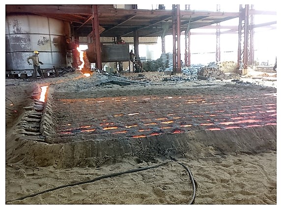
The factory manufactures Pig Iron which is an intermediate product manufactured by smelting iron ore with high carbon fuel such as coke usually with limestone as flux. As seen in Fig.2, the ingots are produced at many a branching structures which are laid in sand at right angles to its central channel called the runner wherein the liquid metal is poured directly from the bottom of the EAF. Such a configuration resembles, in appearance, to a litter of piglets suckling on a sow. As the metal cools and hardens the branching ingots, the Pigs, simply break away from the much thinner runner, the Sow, hence the name Pig Iron.
The high carbon content 3.5%-4.5% makes it brittle. Being an intermediate product it is intended for re-melting, and thus the uneven ingot size and inclusion of small amount of sand are not significant as compared to the ease of its casting and handling. Pig Iron is used traditionally and primarily in foundry industry and to some extent in induction furnace industry for producing specific grade of iron billets.
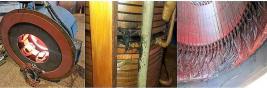
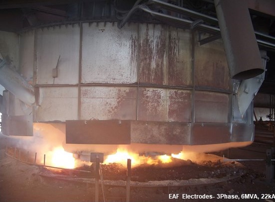
The EAF is powered from a 3ph, 6.0mva, 33kv/160v, 22kA, 50Hz, transformer as shown in Fig.5, and connects it through a 3ph, 22kA, 160v, copper bus-bar that connects to its three electrodes. The electrodes are then submerged into the charge of iron ore and coke. Thus the electrodes effectively short circuit itself and that cause enormous current (22kA) to flow through the charge. Its effect melts the charge as shown in Fig.1.
The Heat control into the charge is done by electrode positioning lowering it increase, and raising it decrease the heat and also the power demand. A Semiautomatic control system continuously positions the electrodes at an appropriate depth into the charge for the optimum heat and power demand. The charge is continuously fed into the EAF from its top hopper. The liquid metal is however tapped from its bottom in a batch process at every interval of about 3-1/2hrs as shown in Fig.2, producing 6.5Tons per batch and summing up to 45tons per day in seven batches.
There however is a problem to overcome with EAF for iron ore melting. Iron ore fines and that in particular from Indian mines have about 56% Fe content. It is not enough a conductivity that can create effective short circuit between its three electrodes, which requires a minimum 65% Fe content.
The problem is solved by pre-processing the iron ore and thereby increasing its Fe content; wherein it is mixed with few percentage of mill scales, and sintered in a hydro cyclone. Sintering is a process of welding together smaller particles of metal by applying heat below its melting point. It is a simple process that requires no direct electricity. The initial heat is generated by using some waste materials like packaging waste, rice husk etc., and then the flame is carried through by oxygen lancing which is achieved by drawing ambient air through the sintered mixture using ID Fan.
Mill Scale is hardened oxidized surface that gets developed on the steel surface when it is hot processed. It contains 98% Fe in the forms of iron and oxidized iron namely Fe, FeO, Fe2O3 and Fe3O4. It is a bye-product from hot rolled milling process. It gets developed when a heated steel ingot is hot rolled into a long sheet. High-pressure water jets at about 70 bar descale it and drop it down from the steel surface. It is a scale and it peels off as flake off the hot rolled steel surface. Mill scale is a waste that gets generated in large integrated steel plants.
III. CASE STUDY
A. Problem Statement
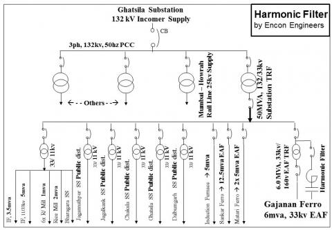
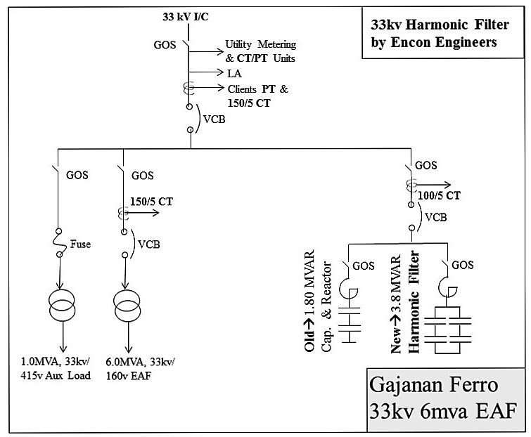
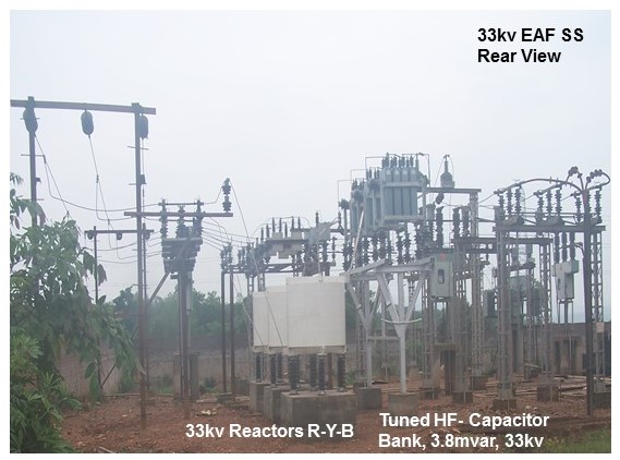
Firstly, low fault level, thanks to its remote location near a forest land. Secondly, high power quality harmonic disturbances, from a hyperactive Howrah-Mumbai railway traction line that passes beside it and receives 25kv supply from the same nearby 132/33kv Ghatsila Substation as shown in Fig.3 (The top caption picture).
Furthermore, the conventional engineering design practice is limited in installing only power factor compensation capacitors for linear loads, and capacitors with detuned reactors for non linear loads (NLL). The same design practice is also followed here considering that by the EAF as NLL.
The factory receives power form a 50mva, 132/33kv, TRF at Ghatsila Substation that also supplies to several other surrounding industries namely, 2x Pig Iron plants, 1x Induction Furnace plant, 6x Public Distribution substations each through a 33/11kv sub-distributions, 7x Rice Mills each through a 33/11kv sub distributions and 2x Induction Furnace plants each through a 33/11kv sub-distribution.
If the NLL is present in the power system then connecting PF capacitors with current-limiting reactors or with detuned reactors, without having the least check on its resonance condition, is a recipe of a potential harmonic resonance problem. It is one of the major causes that defines a stable grid and a stable power system within an industry. The resulting power surge that mainly manifest as voltage sags and fluctuations, as the consequence of power quality harmonic resonance, is the single most major cause that inflicts billions of dollar damages in terms of industrial equipment failures and productivity losses every year worldwide. Electrical harmonics are unpredictable. Under favorable power system impedance, the triggered harmonic resonance situation, magnifies both the harmonics and the power fluctuations within the grid supply. The factory was then barely 6-months from its startup commissioning and reported extensive power quality disturbance and equipment failures during our onsite harmonic study.
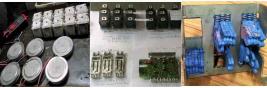
1. 33kv capacitor failure: It had installed 1800+1200kvar capacitor banks with detuned reactors from a MNC company for maintaining plant PF near at UNITY level. The capacitors started bulging from all sides thereby reducing its effective kVAr output and the plant power factor, and eventually it started blasting one by one with time. We observed that the smaller 1200kva bank had failed completely and the bigger 1800kvar bank partially.
2. HPMV ballast failure: Lighting ballasts were burning regularly.
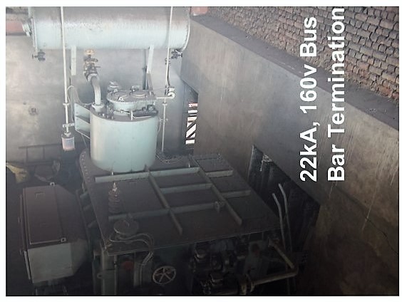
EAF transformer, 6mva, 33kv/160v, 50hzFig.5 EAF Transformer 6mva 33kv/160v 50Hz
3. 33kv HT Fuse failure: The EAF auxiliary load is powered from a 1.0mva, 33/0.415kv, 50Hz Transformer. It is connected at the upstream at 33kv main incomer PCC through a 33kv HT fuse as shown in Fig.4. The fuse was blowing frequently at regular intervals which in turn used to trip the electric arc furnace.
4. AC Motor overheating and failure: The EAF auxiliary load includes several constant speed squirrel case induction motors, SQIM, for applications like in EOT cranes, cooling tower fans, condenser water pumps, air compressors and other utilities. Almost all 3ph, 50hz, 415v LT motors used to overheat frequently and that eventually used to burn its stator winding insulation.
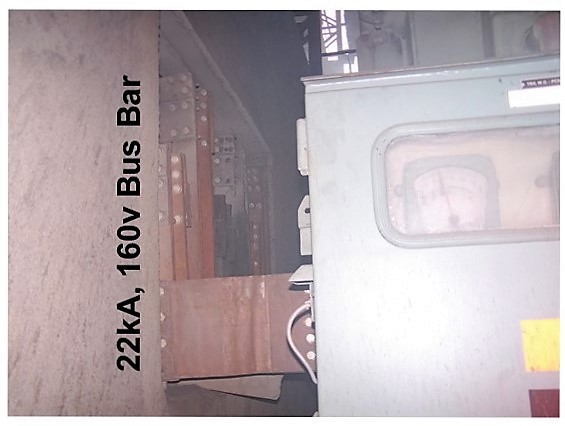
5. The Gigantic 22kA copper bus-bar used to overheat and vibrate: The 22kA copper bus-bar that connects to the 3phase electrodes of the EAF, used to overheat visibly red-hot and vibrate audibly loosening its nuts & bolts. The phenomenon used to happen in about once a month. The problem persisted even after ensuring that all bus bar nuts & bolts were tight and thereafter even after replacing those nuts and bolts, and brazing and solidly fixing the affected bus bar plates. The continued vibrations and rubbing between the bus bar plates wore out the affected bus bar section. Those then were replaced with new bus bar plates, but the problem still continued. The 22KA bus-bar termination at the 160v, EAF transformer secondary side is shown in Fig.5 and the 22kA bus bar in Fig.5a.
6. 6mva EAF TRF high winding temperature: The transformer winding temperature reached as high as 90oC even though it could not be loaded beyond 5mva due to the existed problems. The prevailing conditions were ideal enough for a potential failure of the EAF transformer itself. Transformers are susceptible to current harmonic distortions that can melt open its HV winding and create a single or multiple phase faults usually an open circuit with or without earth fault. Transformers are also susceptible to voltage harmonic distortions and power quality harmonic resonance conditions that can burn its winding insulation either at HT or LT or can cause an earth fault between its winding and body or at OLTC terminals. Most heavy industries like metal have a history of such high voltage transformer winding failures
B. Harmonic Study and Root Cause Analysis
The Power Quality harmonic measurements were carried out during Apr.2012 using a high quality 3phase power quality harmonic analyzer of type PowerPro which measures at a sampling rate of 256/cycle and calculates RMS value of all measured parameters at every cycle basis. It measures all steady state power parameters, power quality including individual phase and neutral harmonics up to 64th, THDi, THDv, Inrush current, waveform distortions and voltage and current spikes with 65uS precision. Further details of the instrument could be obtained at www.candura.com.
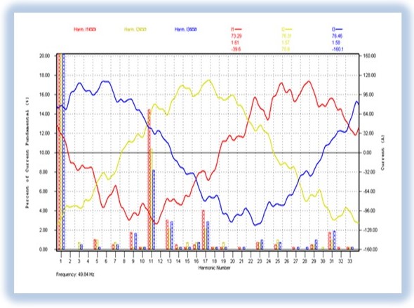
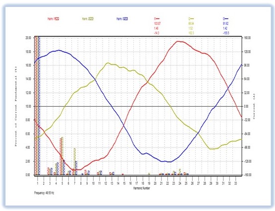
It was observed that the power system of the incoming grid supply was tending towards a higher harmonic resonance condition which was the primary reason for the about once a month runaway harmonic resonance that used to cause the huge overheating and vibration of the gigantic 22kA copper bus bar of the EAF transformer. An electrical power system with an induced harmonic resonance condition can cause dissipation and/or oscillation of huge amount of energy. This was the root cause for the bus bar to get visibly red hot and vibrate audibly loud; combination of which used to loosen the buts and bolts of the bus bar, no matter how tightly it was held The measured harmonics of both current and voltage along with its distorted waveforms are shown in Fig.6 and 7 respectively.
The current waveform at 33kv incoming grid PCC was highly distorted with 14.8% THDi with 125A peak load current and 11th (I11) and 17th (I17) as major current harmonics as shown in Fig.6.
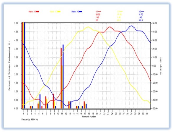
The voltage waveform at the 33kv incoming grid PCC was only moderately distorted and was well within IEEE 519 limits with 3.9% THDv at 47kv peak load voltage (RMS value of rated line voltage is 33kv) and 11th (V11) and 5th (V5) as major voltage harmonics as shown in Fig.7.
It was evident from these measured harmonic bar charts and waveform graphs that a part of the incoming grid which was supplied through the 50mva Transformer feeder of the Ghatsila substation was under harmonic resonance condition. The 11th harmonic number is not a natural harmonic that an EAF of this specification could generate. Its real cause was the capacitors with detuned reactors installed by the factory and may be by many other surrounding industries within the same electrical power system.
A combination of these was tending towards a series harmonic resonance condition by the interaction with the grid power supply. Once an electrical power system gets subjected to a harmonic resonance condition it magnifies both the current and the voltage harmonics, cause voltage sag and fluctuations, and energy swings. The extent of it depends upon the conditions which exist then within the effective zone of the electrical power system and its then load conditions. These parameters vary continuously, and so are the conditions, duration and the extent of the grid instability along with its harmonic magnifications.
This root cause diagnosis derived from the onsite harmonic analysis was further cross checked with the failure records as detailed under problem statement. The nature of electrical failures and the ways those were happening were in consonance with the fact of existence of a harmonic resonance condition with the incoming grid supply.
C. The Solution, Passive Tuned Harmonic Filter (HF)
The best possible approach for solving harmonic resonance problem is to install a passive tuned harmonic filter closer to the final load point which in this case was at the 3ph, 160v, 22kA, electric arc furnace transformer's secondary supply PCC. This 160v LT bus bar was connected to the 3phase electrodes of the EAF which was the final load point. Also, the 6mva, 33kv/ 160v EAF transformer would provide an isolation in between the grid and the factory. Such an isolation makes it relatively easier to tackle a potential series harmonic resonance phenomenon with lesser design complexities; than designing it without the advantage of having that isolation transformer, since it greatly isolated the factory load from the other loads within the same effective grid supply zone.
However 160v is too low a voltage and 22kA is too high a load current which would have rendered the LT passive harmonic filter project commercially unviable even after considering higher energy efficiency and higher productivity those usually accrue when harmonic filters are installed closer to load point, as compared to upstream at a higher bus voltage.
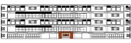
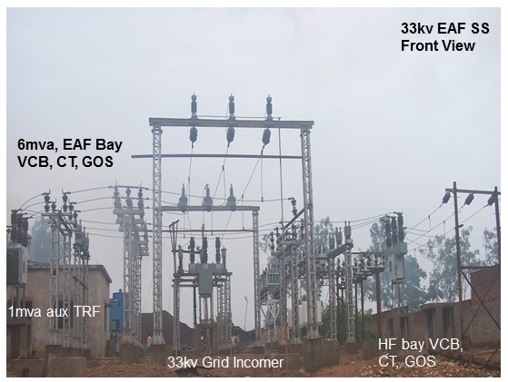
Practically the solution got limited to tuning and realigning the incoming grid's power system impedance at its 33kv PCC starting from the 50mva grid Transformer supply at Ghatsila substation. It required installing the harmonic filter at the 33kv PCC which also happened to be the grid as shown in Fig.3., the top caption picture.
The installed harmonic filter would thus not only cater to the factory's own NLL but also to a larger grid supply zone to the extent those are connected with the same 50mva grid TRF. In-addition harmonics are called nonlinear loads for all the good reasons. It does not like to contain itself within a transformer isolated zone and its transgression within an effective and larger power supply zone are very common. Its extent is again continually variable in line with the associated electrical power system and its load conditions.
We have had past experiences of trouble from such installations. Which further gets compounded due to the lack of motivation for harmonic suppression among other neighboring factories. Given nonlinear nature of the harmonic resonance, it is very much possible that some factories get affected very hard and some may not be as hard to have taken a note of it. The total voltage harmonic distortion (THDv) at the affected 33kV grid supply zone could reach intermittently as high as 40% plus under resonance with a favorable power system impedance at that instant, and in combination with nonlinear loads and capacitor switching by the surrounding factories.
The resultant resonance causes vibration noise overheat and occasional TRF HV winding failures. The recorded details of severely distorted 33kv grid supply under such harmonic resonance conditions could be obtained from www.enconengineers.in. The harmonic filter was installed at the 33kv PCC of the factory at its outdoor substation, which is also 33kv grid supply, as shown in Fig.8 (front view) and Fig.9 (rear view).
D. Results Achieved.
After the installation of 33kv harmonic filter at the grid incomer at the factory's outdoor substation about a year ago, a repeat harmonic study was carried out.
The current waveform at the 33kv grid incomer PCC was controlled within 6% THDi, at 152A peak load current and I5 and I7 as major current harmonics as shown in Fig.10. The unbalance in the 3ph waveforms in current magnitudes is due to the unequal arcing among the three electrodes of the EAF.
The voltage waveform at the 33kv grid incomer PCC was controlled well within IEEE 519 norm at 2% THDv at 45.6kv-peak load voltage (RMS value of rated line voltage is 33kv) and V7 and V23 as major voltage harmonics as shown in Fig.11.

Thereafter the factory performance was observed closely for over a year. All power quality harmonic disturbances and equipment failure issues all got resolved and the unusual resonance problem with the gigantic 22kA bus bar overheating and vibration did not occur thereafter indicating that the chances of a severe power quality harmonic resonance is greatly reduced. However, looking at the THDv waveform as in Fig.11 on the post harmonic solution scenario, there remains some chance for a possible resonance and that's why it is said that resonance can't be eliminated but can only be shifted away from a working frequency bandwidth.
The problem arose here were not due to an ordinary power quality harmonic issue. The current harmonic distortions (THDi) were not high enough to cause such an unusual harmonic problem and the voltage harmonic distortions (THDv) were well within IEEE 519 limits, as found during the initial power quality harmonic measurement. A portion of the grid supply zone starting from the 50mva, 132/33 Transformer at the supplying Ghatsila Substation was on the boundary lines of its power system's stability.
IV. CONCLUSION
The enumerated case study and its yearlong performance verification report clearly establish all round improvement of major power system parameters not only inside the plant but also within the effective grid supply zone.
Doing the power quality engineering at the downstream of a plant with major NLL mirrors optimum grid conditions. An engineering effort that will greatly prevent electrical pollutions from entering the electrical power system of the grid.
In-addition, it reduces carbon emission by enhancing productivity, removing barriers to energy efficiency, and promoting efficient use of energy all along. That starts from downstream plant to neighboring users, and up to the upstream power plant, the IPP power supplier and the grid company.
The cost saving when looked narrowly in comparison with the electricity bill alone might seem moderate. But when compared holistically with substantially reduced investment cost, lower carbon footprint, uninterrupted production, MTBF, inventory cost of components and workforce motivation coupled with ever rising cost of energy, the economic benefits would far outweigh the cost of the solution.
 V. BIOGRAPHIES
Kanai Banerjee graduated in Electrical Engineering from Bengal Engineering and Science University, Shibpur, India in the year 1983.
Worked at Bharat Heavy Electricals Limited from '83 to '95 and thereafter as a promoter at Encon Engineers still date.
His special fields of interest include power quality engineering, harmonic solutions and manufacturing passive tuned harmonic filter and triplen harmonic filter of all size LV and HV, troubleshooting failures, energy conservation, electrical consultancy and HVAC engineering for setting up truly green building and retrofitting large centralized HVAC projects.
He has been instrumental in building up the company's impressive growth and reputation as a knowledge-based technology solution provider on power quality, energy efficiency, process optimization and in Total Power Management fields.
An energy auditor certified by the bureau of energy efficiency under the ministry of power government of India, a member and chartered professional engineer with the institute of engineers India, a member at the Indian society of heating, refrigerating and air-conditioning engineers, ISHRAE and a member at the Canadian and American EMTP-ATP user group.
Place: Bangalore
Date: 15th July 2013