

Generator Failure
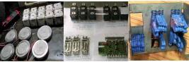
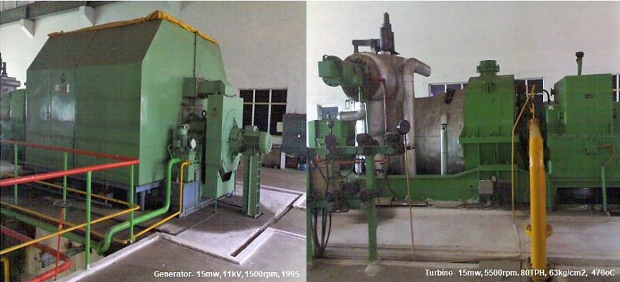
Major generator failure concerns are over-excitation during load-rejection wherein V/F ratio could be excessive and dead generator excitation protection. Increase in voltage/frequency ratio subjects a generator to higher flux-density level than it's designed for. Sudden load throw-off in the grid increase voltage at the generator terminal. The increased V/F ratio could cause saturation and inducement of stray flux in the generator's magnetic core. In turn, it leads to overheating and winding insulation failure. If a dead generator is accidentally switched-on it will behave as an induction motor, but its rotor is not designed to turn the prime mover from a cold start. During acceleration very high current will get induced in the rotor. That will burn the generator winding instantly. Followings are a typical turbine-generator (TG) relay protection panel for a 6MW, 11kV Alternator.
1. 51V Voltage controlled over current relay, make GEC Alstom. Relay function, operation & settings details: Over current relay type CDV; Vn =110v, 50hz UV = 33v (t scale = 0 to 80sec); Vx =110- 125v dc. Instantaneous O/C scale 2.5 to 20 (usually 5-times O/C). Settings= Element1 to 3, O/C amps 1.0A (relay scale 0.5 to 2A). Time setting IDMT curve x Scale factor (0 to .1 to 1).
The voltage controlled (also voltage restrained) O/C relay is specifically designed for Generator backup protection. When the synchronous reactance of a generator is large enough to cause a sustained short circuit current lesser than its full load current, the presence of a fault is detected through an under-voltage element and the relay setting is adjusted accordingly. Both its under-voltage and over-current elements are independently adjustable which makes it a preferable choice over the voltage restrained relay. When the bus voltage drops below the set value, the under-voltage element permits the operation of the time overcurrent unit. It thus provides backup protection for a fault not cleared by the system's primary relays.
When the generator voltage does not drop significantly below the rated voltage, voltage restrained over-current relay provides faster backup protection. The voltage-restraint over current relay has a voltage element that functions as a pseudo-impedance relay, and provides a restraining torque which is inversely proportional to bus voltage. It shifts the relay pickup current which becomes sensitive to larger voltage drop. It negates current-input produced torque and rides through permissible power swings at nominal voltage. It discriminates between a close-in fault, lower the voltage faster the response, and a remote one, higher the voltage slower the response. Voltage restrained O/C relays are not used wherein generators are grounded with Neutral Grounding Resistance (NGR), or in an earthed system.
2. 87A, B, C Instantaneous Differential relay (3 elements), make GEC Alstom. Relay function, operations and settings details: Differential relay type CAG. Rated CT Sec, In =1A, 110v, 50hz Setting = Ir, Iy, Ib (3-elements) = 0.2A (scale 0.1 to 0.4A).
Current differential relays are used to protect large generator, transformer, and motor. It detects low-level winding to ground fault and is essential in protecting equipment damage. In 87 electromechanical relays, each phase current from both CT branches pass through restraint winding (label 'R') and are summed up in the middle T-junction. The sum current is then directed through an operating winding (label 'O') whose magnitude must be above the "percentage set value" (typically 10% to 50%) of the current through the restraint winding, for the relay to operate. Specific connection rules apply for Delta/ Star Transformer for cancelling the phase shift. CTs at the Delta side primary are connected in Star, and at Star side secondary are connected in Delta.
For differential busbar protection, every outgoing feeder's CT are connected in parallel. All S1 CT terminals are shorted and so as all S2 CT terminals. The 87 Relay is then connected between the S1 and S2 terminals wherein as per Kirchhoff's law, no-current will flow under normal operation or with any fault outside the busbar, since the sum of all CT currents must be zero. However, in case of a fault within the busbar, the fault current will flow without being measured by the differential protection CT combinations, and thus current will flow through the 87 Relay. For differential protection of sectionalized busbar, say Section-A and Section-B with one bus coupler; in-addition another CT closest to the bus coupler circuit breaker of Section-A is taken and the protection configuration with 87A Relay would provide differential protection for Section-A of the busbar. Similarly, another protection configuration with 87B Relay would provide differential protection for Section-B of the busbar.
3. 86G Tripping relay for Generator, make GEC Alstom. Relay functions, operation abd setting details: Tripping relay type VAJ (2 element) for Generator, Operating voltage 110 to 125v dc
4. 86T Tripping relay for Turbine, make GEC Alstom. Relay function, operation and settings details: Tripping relay type VAJ (2 element) for Turbine, Operating voltage 110 to 125v dc.
5. 51N Earth-Fault relay, make GEC Alstom. Relay function, operation and settings details: EF relay inverse type CDG. Instantaneous O/C scale 2.5 to 20 (usually 5-times O/C). Setting= EF relay amps= 0.1A (relay scale 0.1 to 0.4A). Time setting IDMT curve X Scale factor (0 to .1 to 1).
6. 64R Rotor first earth fault protection relay, make GEC Alstom. Relay function, operation, and setting details: Rotor first EF protections relay type VAEM MK II. Rotor Voltage 0 to 550v dc (if E/F passes through Rotor, it sends 30v dc which is factory set for tripping this EF Relay). Relay Aux Volt 230/240v AC.
The rotor earth fault relay is used in a synchronous generator or motor to detect the presence of an earth fault in its rotor winding. The rotor of a synchronous alternator or motor is wound by its field winding. While the winding is insulated from the ground but the rotor is subjected to heat and vibration which could cause the winding to give up at a place, and the winding can get earthed. While the first earth fault in the rotor winding is not damaging but it sets the stage for a damage if a second earth fault occurs. That would cause a short-circuiting through the rotor causing excessive vibrations and making the rotor shaft eccentric. In extreme case those forces could damage/ fail the rotor shaft and its bearing.
In DC injection method of the rotor earth fault protection, the positive terminal of the DC voltage sensitive 64 relay (with a series resistor) is connected to the (+ve) terminal of Exciter and through it to the (+ve) terminal of the rotor field winding. The other negative terminal of the 64 relay is connected to the (-ve) terminal of an external DC source obtained through an external Bridge Rectifier (4-terminals). The (+ve) terminal of the Bridge Rectifier is connected to earth/ground. Through the other two power input terminals of the Bridge Rectifier is connected, an auxiliary AC supply through an auxiliary transformer.
In the event of an earth fault either in the rotor field winding or in the exciter, the (+) terminal of the external DC source would appear at the (+) terminal of the 64 Relay, as it is connected at the positive terminal of the exciter and the rotor field winding, and would activate the voltage sensitive 64 Relay. 64 is an ANSI function for detecting ground/earth fault due to breakdown of insulation.
7. 60A Voltage Balancing relay, make GEC Alstom. Relay function, operation, and setting details: Voltage balancing relay (2-elements 60AA & 60AC) type MVAPM, Vn = 110v, 50hz ac. Operating voltage 110 to 125v dc OR 220 to 250v 50hz, ac
8. 60B Voltage Balancing relay, make GEC Alstom. Relay function, operation, and settings detail: Voltage balancing relay (2-elements 60BA & 60BC) type MVAPM, Vn = 110v, 50hz ac. Operating voltage 110 to 125v dc OR 220 to 250v 50hz, ac.
9. 81 Under Frequency and Over Frequency Relay type MFVUM, SEG make. Relay function, operation and setting details (U/F and O/F relays); Vx = 110 to 125v dc. E1) t1= (0.1+ Sum)Sec T1 2109, f1 = 105/T1 Hz. E2) t2 = (0.1+ Sum)Sec T2 1923, f2 = 105/T2 Hz .
10. 46 Negative Phase Sequence relay, Relay function, operation & setting details: (-VE) Phase Sequence relay type CTNM. Nominal Amps In = 1A, 50hz, ac; Auxiliary voltage 110v to 125v dc.
Settings (R, Y, B, 3 elements) = Scale I2s= 5% (k3=1), 7, 5% (k3=2.25), 10% (4), 15% (9), 20% (16).
Set at 7.5% (Alarm) and 10% (Trip); k1 value at 1.2 (scale 1 to 10). (I2s/ In) 2 t = k1k3;
11. 95 Trip circuit supervision relays, make GEC Alstom. Relay function, operation & settings detail:
Trip circuit supervision relay type VAX MK II. Settings: Element1= Vx (A) 110 to 125v dc, Element2= Vx (C) 110 to 125v dc. Element3= Vx (B) 110 to 125v dc.
12. 86G 95G Trip circuit supervision relay, make GEC Alstom. Relay function, operation & settings detail: Trip ckt supervision relay type VAX MK II. Settings: Element1-2= 95A/ 86G 95C/ 86G.
13. 86T 95T Trip circuit supervision relay, make GEC Alstom. Relay function, operation & settings detail: Trip ckt supervision relay type VAX MK II. Settings: Element1-2= 95A/ 86T 95C/ 86T
14. 2/40 T1 Timer Field Fail relay, make GEC Alstom. Relay function, operation & settings detail: Timer field failed definite type relay type VTT, Vx = 110 to 125v dc. Settings: Delay on pick up 2sec (relay scale 1 to 10sec) with external resistor.
15. 2/40 T2 Timer Field Fail relay, make GEC Alstom. Relay function, operation & settings detail: Timer field failed definite type relay type VTT, Vx = 110 to 125v dc. Settings: Delay on drop off 10sec (relay scale 1 to 25sec) with external resistor.
16. 80DC DC Relay Supervision relay, make GEC Alstom. Relay function, operation & settings detail: DC Relay supervision relay (2 elements) type VAA, Aux Volt = 230/ 240v 50hz ac, LH volts =110v dc.
17. 27P Excitation Fuse Failure relay, make GEC Alstom. Relay function, operation & settings detail: No volt relay type VAG, Nominal voltage = 110v, 50hz, ac. Drop off volts 27.5 to 66v, 50hz.
18. 32P Active Power Relay, make GEC Alstom. Relay function, operation & settings detail: Definite type Reverse Power Relay type CCUM. CT secondary 1A, 110v, 50hz; Max torque phase angle 30deg; Aux. Volts = 110 to 125vdc. Definite time relay type VTT. Settings: Delay on pick up 2sec (relay scale 1 to 10sec) with an external resistor.
19. 59 Over Current Protection relay (2 elements), make GEC Alstom. Relay function, operation, and settings detail: Instantaneous OC relay type VAGM. Settings: 126.5v (relay scale 121 to 154 volts).
ABB's REM 545 is a modern-day numeric relay with a Non-Directional Over Current (NOC) component, among other relay functions. The numeric NOC relay setting has three components. NOC (low) = 1.1 to 1.25 x In, with a tripping time between 1 to 3sec on a normal-inverse scale. NOC (high) = 1.25 to 2 x In with 0.1 to 1Sec Definite Time trip. NOC (inst) = 2 to 5 x In on an instantaneous trip time of 50 to 800ms. However, the instantaneous NOC setting at the generator terminal may trip both the Grid incomer and generator breakers and cause a blackout.
20. 27 Inverse Time Under Voltage Protection relay, make GEC Alstom. Relay function, operation and settings detail: U/V relay type VDG (Aux volts = 24 to 250v dc). Settings: 99volts (relay scale 55 to 99 volts); Time setting IDMT curve x Scale factor (0 to .1 to 1).
21. 40 Field Failure Protection relay, make GEC Alstom. Relay function, operation & settings detail: Field failure protection relay type YCGF. Settings: K1 0.85 (0.75 - 1.0) K2 7.5 (5.0 - 20); K3 5 (0 - 5) K4 2.5 (2.5 - 15) K5 129.5 (34.75 -250); Z1 = k3 + k4 = k2 ohm; Z2 = k1 x k5 ohm = Setting (0.85 x 129.5).
22. 32Q Reactive Power relay, make GEC Alstom. Relay function, operation & settings detail: Definite type Reverse Power relay type CCUM. CT secondary 1A, 110v, 50hz; Max torque phase angle 30deg; Aux. Volts = 110 to 125vdc. Definite time relay type VTT. Settings: Delay on pick up 3sec (relay scale 1 to 10sec) with external resistor.
23. 2/59 Timer Over Voltage protection relay, make GEC Alstom. Relay function, operation and settings detail. Definite time relay type VTT. Settings: Delay on Pick up 4.25sec (relay scale 0.5 to 5 sec).
24. 40X Auxiliary Field Failure protection relay (1 element), make GEC Alstom. Relay function, operation & settings detail: Auxiliary relay type VAA, LH volts = 110 to 125v dc.
25. 27/40 UV relay with field failure protection relay (2 elements), make GEC Alstom. Relay function, operation & settings detail: Instantaneous UV relay type VAG, Aux volts = 110 to 125v dc. Settings Drop off volts = 70volts, Nominal PT voltage = 110v, 50hz.