
Harmonic Filter
When super tuned, the electrical harmonic filter turns a multitasker that eliminates harmonics, maintains power system stability by mitigating power surge, voltage fluctuation and resonance. A super tuned harmonic filter is an engineering tool that prevents power plant blackout by stabilizing power system parameters for a successful grid de-synchronization, and islanding power generators on utility power failure. Besides, it relives station generators from momentary voltage fluctuations and power surges over a grid or internal power disturbance which helps in eliminating premature winding insulation failure of the generator.
A quality harmonic filter panel is custom-built for the project needs with incremental costs and complexities. In its basic specification, it provides a low impedance parallel path which enables current harmonics from its source at downstream loads to flow into it and allows a tolerable level of current harmonics, within IEEE-519 norm, to flow into the upstream utility grid. However, basic harmonic filters can't control high harmonic levels. Whereas, a top-end harmonic filter mitigates both current and voltage harmonic distortion from any higher level to within limits.
Harmonic Filter, a Video Presentation
https://www.youtube.com/watch?v=Cz_wkugwv3A
Harmonic Filter - a fact check on common misconceptions
There are misconceptions in the minds of even expert consultants and engineers which result in their hyping-up not only fancy specification but installing unsuitable harmonic filter type.
1. The myth is higher current harmonic 80% is dangerous. The fact is if the power of that load is small compare with its supply transformer, it does not need a harmonic filtering solution. It's important to note the total current harmonics at the transformer-end and history of equipment failures and tripping within the transformer. If transformer-end harmonics are near 8% and no-failure history, a de-tuned filter does the job of achieving power factor correction though it does not mitigate harmonic distortions.
2. The myth is high voltage harmonics 40% can't be corrected. The fact is any higher voltage harmonic is controllable with a correctly designed harmonic filter type.
3. The myth is, a harmonic filter at each variable frequency drive end is the best solution. The fact is it's the worst selection if the transformer has many variable speed drives.
4. The myth is the series passive harmonic filter wherein current goes through it, reduces current harmonics within norms. The fact is it can't do beyond a few percentages. It increases impedance in the harmonic flow path that impedes little harmonic. But by doing so, it increases voltage harmonic though.
5. The myth is it's required to eliminate all 2nd to 51st harmonics. The fact is the elimination of a handful of harmonic numbers is enough to limit the total harmonic distortion within IEEE-519 limits.
6. The myth is an active harmonic filter does three-phase load balancing. The fact is AHF injects anti-harmonic current to cancel downstream load harmonics within its rated capacity. But it can't compensate for unbalance load.
Harmonic Filter - hallmarks of top-end custom made design
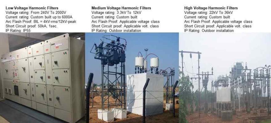
The custom made Passive harmonic filter, super tuned type, is the top-end fit-for-purpose harmonic filter in an electric power system. Its application is diverse across all industry, data center, utility company, co-generation power-plant, renewable energy, grid-tied solar power plant and commercial facilities. It's scale-able, built for any size 10A to 5000A for low voltages- 120volts to 480volts, 525V to 2100V for mill-duty motors-ac vsd or dc and induction-furnaces, and 3.3kv to 36kv for medium to high voltage applications.
It's flexible in installation - suitable for connection at a point-of-common-coupling for a large group of linear and non-linear-loads. OEM recommends to connect it at transformer PCC for the whole group of harmonic and other loads. Besides, if a transformer has a few VFD/VSD drives, it is suitable for individual drive-end connection.
It's variable as per project need and automatic in operation. It eliminates harmonic distortions - both current and voltage, reconstructs distorted sine waveform to sinusoidal voltage and current waveform improving quality of power, improves power factor to near unity.
It eliminates failure and nuisance tripping in plant and machinery both in electrical equipment - generator, transformer, switchgear and in critical plant loads - variable frequency drive, dc drive, control system, computer, server. By providing an improved power quality, it minimises end-product-quality rejection.
Harmonic Filter - a tool that prevents Arc Flash
A mandate that is increasingly becoming noticeable among electrical engineers and safety regulators is the NEPA 70E standard. Besides, the Occupational Safety and Health Administration (OSHA) issues citations based on the requirement NEPA 70E. It stipulates employers to protect employees from arc flash hazard while working in an electrical system by wearing Switching Arc-Flash Suit. We are using non-linear-loads (NLL) since the 1970s, but the arc flash issue came into prominence much later since the year 2005. What has changed since then?
Arc flash and electrical blast - why it's happening now?
By now, we have expanded our use of variable frequency drive (VFD) also called variable speed drive (VSD). Then, we used speed control for critical process load that required matching speed variation. We then preferred DC drive over VFD drive which did not make use of high-frequency switching, the IGBTs. Today, we use variable-speed drives engaging high-frequency IGBT at every other motor load. We save energy using VFD drives for energy conservation projects. We achieve conditions for our comfort by utilising it in HVAC and air-conditioning projects.
Arc flash - what's the Root Cause?
The switching frequency (also called carrier frequency) of a VFD drive is the rate at which it's DC bus voltage is switched on and off during pulse width modulation (PWM) process. VFD manufacturers increase switching frequency apparently to reduce audible noise from motor and harmonic generation. VFDs typically operate in between 4-20khz frequency range.
At higher switching frequency, the noise pitch from stator lamination moves higher beyond the human hearing range, so we hear a lower audible noise from the motor. Similarly, at the higher switching frequency, the measurable harmonic generation, typically up to 50th order are lesser, which matters for the sake of meeting regulatory harmonic-norms which do not measure higher and kilo Hz order harmonics.
Harmonics are high-frequency currents and voltages. All frequencies which are odd multiple of three (like 3x50hz, 9x50hz, 27x50hz etc.) are called triplen harmonic currents or voltages. Unlike the fundamental-frequency (50 or 60hz) and other harmonic frequencies; triplen harmonics don't cancel at three-phase neutral but add-up and grow three-fold. The lower order triplen frequencies add-up and increase the neutral current in the electrical power circuit. The arc-flash problem happens with the higher-order triplen-frequencies which add-up to a charged voltage forming an electrical field (potential gradient) around electrical conductors in its power system.
Arc flash - how encon harmonic filter eliminates it
Arc flash phenomenon is similar to the corona effect on high-voltage transmission power lines. It happens when the air around a high voltage electrical conductor ionise to a sufficient potential gradient (electrical field) to form a conductive region. It generates a bluish glow around the air of the current-carrying metal conductor. When the strength of the electrical field is high enough to cause an electrical breakdown, arcing happens to a nearby object at ground potential.
Adding-up of high-frequency triplen-harmonics from the variable frequency drives and other IGBT-based NLL is the precursor of an arc flash. Once it attends sufficient field strength, it arcs to a nearby object at ground potential causing electrical blast involving electrical equipment.
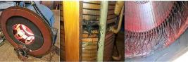
We have troubleshot many dangerous arc flash blasts wherein we found the frequent arcing objects to be switchgear (air circuit breaker, MCCB, Fuse), the body of electrical panel, Bus Bar. The electrical bus bar affects in several ways. Pitting along the bus bar is a common effect. In one incident a portion of bus bar at the junction of horizontal and vertical joint evaporated and vanished in an arc with its body. We built our super tuned harmonic filters with special zero-sequence winding which provides a path to the high-frequency electric field which prevents arcing.
Arc flash solution - a case study
We have written a separate case study for electrical arc flash - read it at Mitigate VFD Harmonics.
Harmonic Filter - Drive wise (Front End) harmonic correction
Drive wise harmonic filtering is called frontend type. When a transformer has a few small size VFD Drives it can be applied. We use a zig-zag winding for the series reactor which ensures minimum voltage drop and prevents harmonic overloading into the main parallel harmonic filter.
In case of a transformer having few higher rating VFD Drives, we apply only parallel harmonic filters across each VFD. If the transformer has too many VFD Drives, our recommendation is to use a single harmonic filter at the transformer incomer bus.
The advantages of using a single harmonic filter for the full transformer loads are substantial. Accurate and calibrated control of power, harmonics and power factor from minimum to full working load of the transformer. A passive harmonic filter can take out harmonics from all downstream VFD Drives. A transformer end single harmonic filter will have larger LC-circuit which is a better device to control power surge and sudden voltage fluctuations than smaller sized drive wise harmonic filters.
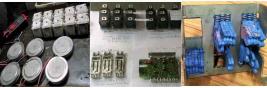
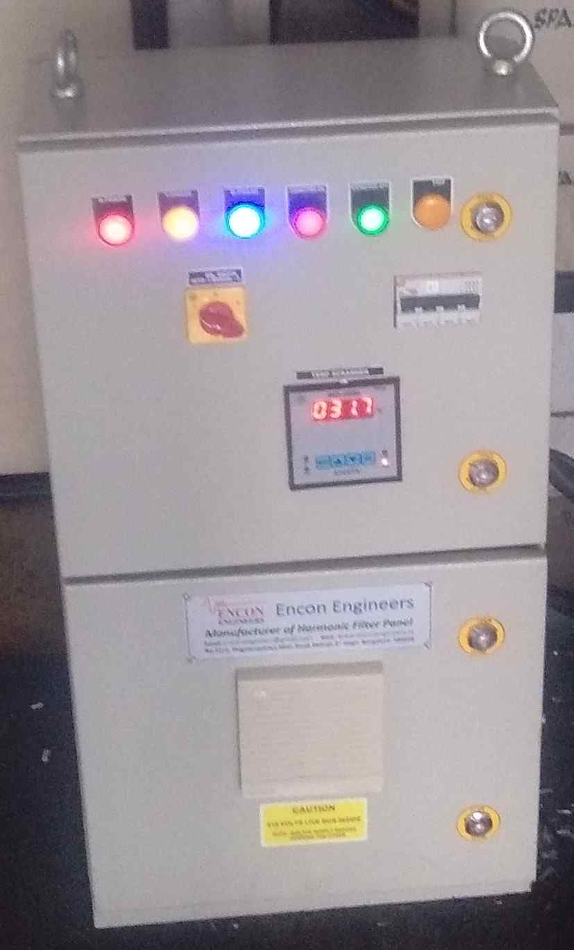
If the application demands, we even use a small parallel filter. As in Fig.1, we have used a 10A harmonic filter in parallel with a VFD Drive for a 30TR package air-conditioner in a corporate building. The AC unit was facing VFD card failure problem.
The industry standard for drive wise harmonic control is different though. Our peers use large series reactors in multiples. Some OEM provides variable tapping. They may not cause much harm when the transformer employs a few small size VFD Drives, even though a no-harmonic solution is a better option.
But when the transformer supplies to large-sized VFDs, the series reactors cause a significant voltage drop that magnifies THDv and disturbs VFD operation. The VFD Drives become too susceptible to voltage fluctuation and even a minor voltage sag trips the VFD.