

Transformer Failure
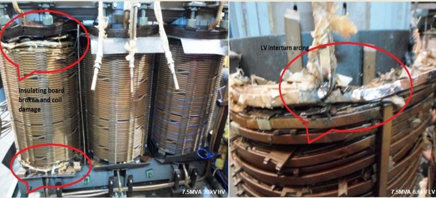
Transformer Failure protection relays & arrestors ensure that it's withstand limits on short-circuit current and power frequency voltages are not exceeded. Impulse over-voltage will happen if lightning stroke falls on an overhead line near the transformer installation. Power frequency over-voltage could occur from the opening of a highly loaded circuit breaker. Transformer insulation protection against these two types of voltage surges are ensured by connecting ZnO type surge arrestor near HV bushing. The most common types of transformer failures happen due to Fault in OLTC, Inter-turn failure and on Loose-clamping. Inter-turn failure happens on shortening of few turns of winding due to overheating, which in turn cause insulation failure. Loose clamping develops with shrinkage of insulating paper blocks in between winding sections, which in turn fails the transformer forcefully on short circuit forces. The followings are 33kv grid side transformer protection relays for a 6.3MVA, 33/11kV grid transformer of a co-generation power plant.
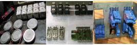
1. 86/95T Trip circuit supervision relay, make GEC Alstom. Relay function, operation and setting details: Trip ckt supervision relay type VAX MK II. Settings= Element1= Vx (A & B) = 110 to 125v dc. Element2= Vx (C)= 110 to 125v dc.
It is used for the continuous trip circuit supervision purpose of both Pre-Closing and Post-Closing conditions in circuit breaker. Detects, alarms, and trips the Circuit Breaker on "Trip Circuit Supply Failure" and "Circuit Breaker Tripping Mechanism Failures" such as loss of voltage, trip circuit connection, low gas pressure in SF6 circuit breaker etc.
2. 86T Lock Out Relay or Master trip relay, make GEC Alstom. Relay function, operation, and settings detail: Tripping relay type VAJ, Operating voltage 110 to 125v dc.
The master trip relay is the main trip relay that trips the circuit breaker. All relay contacts within a relay protection system are connected with a parallel/series circuit to the master trip relay. If any relay within the protection system senses a fault, it energizes the master trip relay which in turn picks up trip coil of the circuit breaker, through an auxiliary protection relay contact, as it can't drive the trip coil current of the circuit breaker. The 86 relay is a lockout, manual reset type, relay to avoid multiple charging of the faulty system with unknown operators.
3. 87T 1 Differential relay for R phase, make GEC Alstom. Relay functions, operations and setting detail: Differential relay type MBCH, Aux voltage 110 to 125vdc. Rated CT Sec, In =1A, 110v, 50hz. Setting = Is = Sum (plug sets, 0.1 to 0.5) x In (set at 0.1A).
Current differential relays are used to protect large generator, transformer, and motor. It detects low-level winding to ground fault and is essential in protecting equipment damage. In 87 electromechanical relays, each phase current from both CT branches pass through restraint winding (label 'R') and are summed up in the middle T-junction. The sum current is then directed through an operating winding (label 'O') whose magnitude must be above the "percentage set value" (typically 10% to 50%) of the current through the restraint winding, for the relay to operate. Specific connection rules apply for Delta/ Star Transformer for cancelling the phase shift. CTs at the Delta side primary are connected in Star, and at Star side secondary are connected in Delta.
For differential busbar protection, every outgoing feeder's CT are connected in parallel. All S1 CT terminals are shorted and so as all S2 CT terminals. The 87 Relay is then connected between the S1 and S2 terminals wherein as per Kirchhoff's law, no-current will flow under normal operation or with any fault outside the busbar, since the sum of all CT currents must be zero. However, in case of a fault within the busbar, the fault current will flow without being measured by the differential protection CT combinations, and thus current will flow through the 87 Relay. For differential protection of sectionalized busbar, say Section-A and Section-B with one bus coupler; in-addition another CT closest to the bus coupler circuit breaker of Section-A is taken and the protection configuration with 87A Relay would provide differential protection for Section-A of the busbar. Similarly, another protection configuration with 87B Relay would provide differential protection for Section-B of the busbar.
4. 87T 2 Differential relay for Y phase, make GEC Alstom. Relay functions, operations and setting detail: Differential relay type MBCH, Aux voltage 110 to 125vdc. Rated CT Sec, In =1A, 110v, 50hz. Setting = Is = Sum (plug sets, 0.1 to 0.5) x In (set at 0.1A).
5. 87T 3 Differential relay for B phase, make GEC Alstom. Relay functions, operations and setting detail: Differential relay type MBCH, Aux voltage 110 to 125vdc. Rated CT Sec, In =1A, 110v, 50hz. Setting = Is = Sum (plug sets, 0.1 to 0.5) x In (set at 0.1A).
6. 64RT Restricted earth fault relay, make GEC Alstom. Relay function, operation, and settings details: Restricted earth fault relay, Rated CT Sec, In =1A, 110v, 50hz. Setting = Is = In 0.1A (relay scale 0.1 to 0.4A); Rext1 (2000ohm).
64 REF Protection: The three secondary CTs in R, Y and B phases and a single NCT (Neutral Current CT) in the transformer neutral to earth/ ground feeder are connected in parallel. All S1 CT terminals are shorted and so as all S2 CT terminals. The 64 Relay is then connected between the S1 and S2 terminals. In case of external fault at the transformer secondary an excess fault current will flow through the affected phase. At the same time, due to ampere-turn balancing effect in the transformer, a balancing current will flow through the NCT. Thus, the net current through the REF 64 Relay would be Zero, and it would not actuate. But during an internal earth fault in the transformer, only the NCT will carry the fault current resulting a current flow through the REF 64 Relay. It is usually an instantaneous over current protection. 64 is an ANSI function for detecting ground/earth fault due to breakdown of insulation.
7. 95T Breaker circuit supervision relay, make GEC Alstom. Relay function, operation and settings details: Trip Ckt Supervision relay type VAX MK II. Settings= Element1= Vx (A)= 110 to 125v dc. Element2= Vx (C)= 110 to 125v dc. Element3= Vx (B)= 110 to 125v dc.
It is used for the continuous trip circuit supervision purpose of both Pre-Closing and Post-Closing conditions in circuit breaker. Detects, alarms, and trips the Circuit Breaker on "Trip Circuit Supply Failure" and "Circuit Breaker Tripping Mechanism Failures" such as loss of voltage, trip circuit connection, low gas pressure in SF6 circuit breaker etc.
8. (50/51 50/51N) Non directional over current and earth (N) fault relay, make GEC Alstom. Relay function, operation and settings details: Non directional over current NOC and Earth Fault E/F relay type CAG. Instantaneous O/C scale 2.5 to 20 (usually 5-times O/C). Settings= Element1, O/C amps= 0.75A (relay scale 0.5 to 2A), Time setting IDMT curve x Scale factor (0 to .1 to 1). Element2, E/F amps 0.1A (relay scale 0.1 to 0.4A), Time setting IDMT curve x Scale factor (0 to .1 to 1).
When a station generator is connected to a grid bus and fault happens at the grid bus away from the station, the non-directional over current (NOC) relay, and in particular the instantaneous (NOC) can act and trip its circuit breaker.
9. AR 1T Aux. relay, make GEC Alstom. Relay functional, operational and settings details: Auxiliary relay type VAA, 3-elements, Aux volts 110 to 125v dc.
10. AR 2T Aux. relay, make GEC Alstom. Relay functional, operational and settings details: Auxiliary relay type VAA, 3-elements, Aux volts 110 to 125v dc.
11. AR 3T Aux. relay, make GEC Alstom. Relay functional, operational and settings details: Auxiliary relay type VAA, 3-elements, Aux volts 110 to 125v dc.
12. AR 4T Aux. relay, make GEC Alstom. Relay functional, operational and settings details: Auxiliary relay type VAA, 3-elements, Aux volts 110 to 125v dc.
13. 51N ST Standby earth (N) fault relay, make GEC Alstom. Relay function, operation and settings detail: Standby EF relay type CDG. Instantaneous O/C scale 2.5 to 20 (usually 5-times O/C). Setting= EF relay amps= 0.1A (relay scale 0.1 to 0.4A). Time setting IDMT curve x Scale factor (0 to .1 to 1).
14. 59T Over voltage relay, make GEC Alstom. Relay function, operation and sets detail: Over voltage relay type VTU definite time, rated voltage 110v 50Hz ac. Settings= %V(t)= 110% (relay scale 9% to 170%). T(sec)= 2sec (relay scale instantaneous to 6 seconds).
15. 27T Under voltage relay, make GEC Alstom. Relay function, operation and setting details: Under voltage relay type UTUM, Normal volt 110v 50Hz ac, Auxiliary voltage 110v to 125v dc. Settings= %V(t)= 90% (relay scale 20% to 90%), t(sec)= 0.5sec (relay scale 0.5 to 6 seconds).
16. 69GT Neutral voltage displacement relay, make GEC Alstom. Relay functional, operational, and setting details: Neutral voltage displacements relay type VDG, Aux Volts 24 to 250v dc. Settings= V(set)= 5.4V (relay scale 5.4 to 20V, 50Hz), t(sec)= 30 x MF (2) = 60sec.
Open Delta Connection: It is common to detect earth fault in an ungrounded three phase system by measuring the displacement that occurs in the neutral voltage winding with an open delta configuration. It's operating principle is to monitor the vector sum of three phase voltages. The RVT or Residual Voltage Transformer's 3phase primary windings are connected in Star and neutral point grounded. Secondary windings are configured in open delta or broken delta connection, wherein only two Delta phases, say R-to-Y and Y-to-B, are shorted/ connected but the third Delta phase B-to-R is opened for connecting the 69G VDG Relay in between. Under normal operation when a balanced 3phase voltage is present at its star connected primary, the voltage across the 69G VDG Relay would be zero. In the event of an earth/ ground fault in one primary phase, the phase-to-ground voltage in the remaining two phases would now be phase-to-phase voltage with a displacement of 60 degree, and the voltage across the open delta and through the 69G VDG relay would become 3V0 or 3times the phase-to-ground voltage. The RVT is marked as 11kv/ root(3) : 110v which means that the transformer is designed to have 110v secondary output voltage in the event of an phase-to-ground fault at its primary. In case RVT is used for Capacitor Bank protection, its primary winding, in-addition, should be designed to carry capacitor discharge current.
17. Universal Test Terminal Blocks for Differential Relays
18. Universal Test Terminals Block for Differentials Relay