
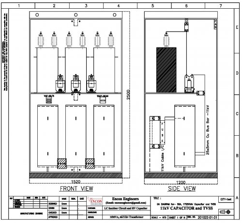
Switching Transient Suppressor using LC Snubber Ckt
Switching transients or TRV appears across Vacuum or SF6 contacts of a circuit breaker while interrupting an inductive load or an overcompensated transmission line with series capacitors. TRV is the voltage that appears across the contacts of a circuit breaker after arc extinction. Unlike Air or Oil circuit breakers the hard-insulation in a Vacuum or SF6 circuit breaker does not allow the arc to develop during its contact separation process. This abrupt chopping of inductive current raises an excessive voltage (TRV) that escalate a re-strike risk. The power system neutral shifts during a fault condition further results in a high amplitude transient recovery voltage. The Rate of Rise of Recovery Voltage (RRRV) is the peak transient Recovery Voltage divided by total time from Zero voltage to Peak voltage. The magnitudes of TRV and RRRV are crucial specifications of a circuit breaker in determining whether it can clear the fault successfully.
While the transient recovery voltage and disturbances come close to Basic Insulation Level (BIL) of MV and HV equipment in industrial and commercial power systems; they do not pose fatal in their first occurrence. But the prolonged exposure to Power Frequency Over Voltage transients (PFOV) weaken insulation and reduce the lifespan of power system equipment. The repetitive transients in medium and high voltage power systems cause transformer HV insulation failure and CT, PT, HT Fuse and Cable blasting. Further, the power system transients percolate through different voltage levels and reach into the low voltage power distribution system. In the LV power system, it causes unwanted tripping and failure in sensitive equipment like AC/DC Drive, Solar Inverter, HMI, SCADA, UPS and Data Center server equipment.
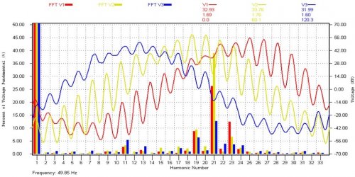
While TRV is a voltage sourced surge, a lightning strike is a current sourced or energy sourced surge. The energy released by a lightning stroke must reach the earth irrespective of path resistance. The current magnitude from a lightning bolt does not reduce along with its flow, but the transient voltage rises following the path resistance. Ferroresonance is another type of transient characterized by a sudden jump in voltage or current. It happens when the power system's inductance (XL) equals capacitance (XC) at a harmonic frequency. The resultant resonance appears typically from few second to tens of minute. Depending upon the extent of the power surge, it can cause minor to devastating damage to power system equipment. Power system study could uncover the signature of a Ferroresonance. The recorded graph depicts a harmonic resonance condition at 21st harmonic frequency on a 33kV utility power supply line.
Why Transformer Insulation Failure is more noticeable at Low Load
When the arc current in a circuit breaker reduces towards zero the instability of the arc chops the current just before natural current zero. The level from which the current spontaneously drops to zero is called Current Chopping. It though happens with all circuit breakers, but with VCB its magnitude is much higher. When VCB contacts interrupt it abruptly chops current due to hard-vacuum insulation. This Current-chopping phenomenon drops the current to zero for a short time just before the natural alternating current comes to zero. Then it continues to flow as Post-Arc Current due to plasma (ionized particles) between the VCB contacts and the influence of TRV, which sweeps the post arc current. When VCB opens, it creates a re-strike at the subsequent current zero which reignites the VCB contacts with a low-value LC-series circuit that results in a high frequency (kHz range) oscillation. L is the cable inductance, and C is the self-capacitance (nano-farad range) of the open-circuited transformer. The transformer insulation comes under attack within a few cycle of this high-frequency oscillation. When VCB opens a light loaded transformer, the current going towards zero is small, and the ionic activity is low, which shuts it off much before the natural current reaches zero. This phenomenon is called Pre-striking, and it leads to a Re-strike that results in a higher TRV magnitude.
How to Mitigate Transients in a Power System - RC Snubber vs LC Snubber
A snubber circuit employs a surge capacitor and a resistor or inductance in series with the capacitor. It connects itself in star in parallel with the high voltage bus bar which could be in star or delta configuration. A Snubber Circuit mitigates all transient types in a power system, including abrupt voltage and power surge with the following characteristics.
1. It attenuates the fast-rising voltage surge by modifying the steepness of the travelling voltage wavefront, thereby bringing down the rate of rising of the damaging impulse voltage. The power system equipment could cope with the reduced rate of change of flux better than applying a steep impulse voltage across it. While capacitors charge, its rate of rising of voltage is (I / C) in kV/uS wherein I is capacitor charging current in kA/uS and C is the capacitance in ufd. Typically capacitors charge to its full voltage within 100uS.
 2. It partially absorbs the surge energy or for that matter the voltage spike. The energy absorbing capacity of a surge capacitor at its peak charge voltage (kV) is 1/2 x ufd x kV2 in Joules. The standardized surge capacitor sizes are 0.125ufd, 0.25ufd and 0.50ufd. Surge capacitors are single bushing type wherein the second terminal connects to the capacitor body. The star-point of the 3phase surge capacitors connects to ground, which introduces a disadvantage of unwanted earth fault tripping.
3. Surge capacitance in ufd range considerably reduce the damaging high-frequency (kHz range) oscillations of the TRV voltage wavefront, damping the ringing. In-addition it favourably tilts its slope giving safety to transformer winding.
4. A resistance in series with the surge capacitor provides a damping effect by lowering the peak amplitude of the oscillation. In-addition it absorbs partial surge energy in the form of I2R loss which also is its undoing. It is a question of when, and not if, the resistance will blast. The standardised value of per phase resistance is 100ohm, but varies from 30ohm to 300ohm with application and voltage level.
5. An inductance in series with the surge capacitor offers several advantages. First, it doubles up as LC-Snubber circuit and HV capacitor for reactive power compensation. The improved Power Factor (PF) reduces current and provides I2R loss saving to the extent of current saving and power system impedance. Second, the LC-Snubber capacitors are double bushing type, and the 3phase star point remains un-grounded, thus eliminates nuisance earth fault tripping. Third, unlike resistance, the inductive impedance increases steeply with high frequency (Xl = 2.PI.Hz.L), thereby provides better damping and flattening of the overshoot. Fourth, needs 50% lower footprint and the additional clearance for heat dissipation not required.