

VFD Harmonic
When VFD drive is sizeable or many, the excessive heat and power surge due to VFD harmonic generated high waveform distortion causes drive failure and unwanted tripping. Read this case study how harmonic filter for VFD solved the problem including an arc flash incident whose root cause detailed in another webpage "harmonic filter powerful with super tuned specification".
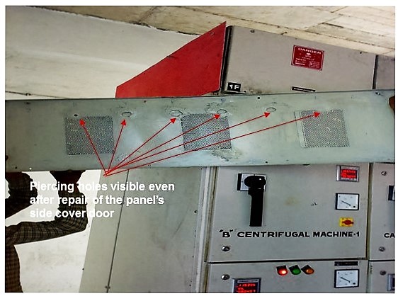
VFD Harmonic forced a power plant to shutdown due to power quality failure. Starting with drive tripping it blasted switch gear, bus bar & electrical panel. This IPP with a 25mw, 11kV, 50Hz power plant and 5000TCD sugar milling unit had completed its first anniversary without harmonic problem. But during 2nd year's operation, it started-off with a massive blast of a 6300A Air Circuit Breaker (ACB). It was at the incomer of an electrical panel. The 415V PCC panel was supplying to sugar plant's process load. There were two such PCC panels connected through a 6300A bus-coupler for the boiling house loads. It had several variable speed drives (VSD). In a span of next 4-week, it sequentially blasted several other switch gears- ACBs and MCCBs. In yet another blast it caused pitting along 6300A double circuit bus bar. It was running at the top-horizontal position inside electrical panel. That also caused 6nos holes at the side cover of electrical panel, as if each bus-bar end had fired a bullet piercing through the panel's metal cover. The power plant's auxiliary VFD loads were powered through a double-secondary transformer. It's earth-pit started boiling surrounding water. A VFD drive's IGBT card failed. It belonged to a 585 kW boiler feed water pump (BFP) motor.
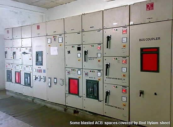
Onsite power quality harmonic analysis revealed an unstable power system zone supplying to this industrial co generation power plant along with a CMV issue. Harmonic Filters, one each at the double secondary transformer supplying to the power plant Aux VFD drives, were installed in the year 2013. In-addition a large 2400A harmonic filter was installed at the sugar plant's process drives' panel as in Fig.1. These measures eliminated all electrical blast and VFD drives' card failure issues both with the power plant's auxiliary load and sugar plant's process drive panel.
Further in the year 2014, 4nos Harmonic Filters were installed individually at sugar Mill drive 1 to Mill 4, each with one 560kw, 690v, VFD drive for reducing harmonic stress with its sugar milling units and thereby enhancing its crushing capacity by 30% to 6500tcd. Another 11kv harmonic filter was also installed at the 2x850kw, 6P, 11kv SRIM Fiberizer drive for energy conservation. Once again another unusual problem surfaced unexpectedly but this time only with the Mill-1 VFD drive and the root cause of that is bound to change the way we design and engineer dielectric insulation protection with our equipment and electrical panels.
Furthermore, the improved power system operative conditions facilitated in increasing productivity sustainably with congruous reduction in the plant's SEC, the specific energy consumption, in terms of kWh/Tons by 15%. It also reduced the power plant's synchronous generator's operating temperature between 3 to 5oC, and enabled additional power export into the 33kv grid.
Index Terms- power quality engineering, harmonic study, root cause analysis, grid stability, power system resonance, power quality harmonic solutions, LT harmonic filter, Medium voltage harmonic filter, HV harmonic filter.
I. NOMENCLATURE
ACB, Air Circuit Breaker, an electrical switch gear
MCCB, Molded Case Circuit Breaker, an switch gear
TRF, Transformer (two or three windings)
SINAMICS, a Trademark of Siemens VFD and drives
ACS 800, a Trademark of ABB VFD drives
THDi, Total harmonic distortions, current
THDv, Total harmonic distortions, voltage
In, Individual current harmonic orders, like 3rd is I3
Vn, Individual voltage harmonic orders, like 5th is V5
II. INTRODUCTION
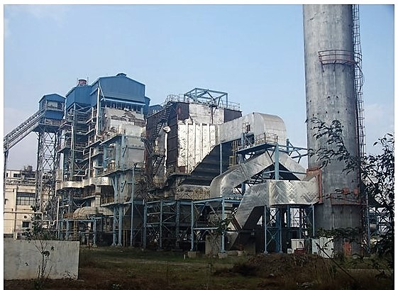
The factory operates its 25mw power plant at 100% capacity with Bagasse as boiler fuel during the sugar milling season which typically is between Oct. to Apr. each year, and thereafter with Coal for the remaining part of the year. It intends to enhance its sugar crushing capacity to 6500tcd, and save enough bagasse during its milling season, and use the same in the power plant boiler during the sugar off season period. This will enable the factory to reduce its power cost considerably. Coal is a costlier fuel in comparison to bagasse which is a bye product from sugar milling process.
Onsite power quality harmonic analysis carried out during Jan.2013. It was done primarily to solve the most pressing issue which was to eliminate the electrical blasting problem. In-addition there were other issues too. The power plant was tripping because of voltage sag and fluctuations from the incoming grid at which it was synchronized at 110kv. It was also tripping the sugar plant's process equipment which were in particular powered through the VFD.
III. CASE STUDY
A. Problem Statement and the Implemented Solution
Firstly, low fault level thanks to its remote location and secondly harmonic loads from its power plant auxiliary VFD drives and other Aux. VFD drives from its sugar manufacturing process PCC panel.
These high frequency harmonics had triggered a power quality harmonic disturbance within its electrical power system. It consists of a 25mw, 11kv, 1500rpm, 50Hz, steam Turbine Generator (TG), a 31.5mva, 11/110kv export transformer at the grid's main incoming PCC, a 130tph, 110kg/cm2, 545oC Boiler with VFD drives for its auxiliary loads, and a 5,000tpd sugar plant with 4sets of 560kw, 690v VFD Mill drives, a set of 2x850kw, 6P,11kv, SRIM Fiberizer drive and a scores of VFD drives in the sugar manufacturing process.
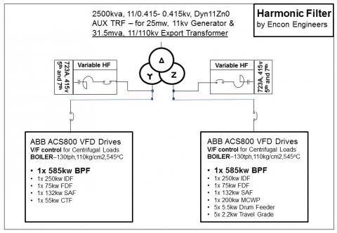
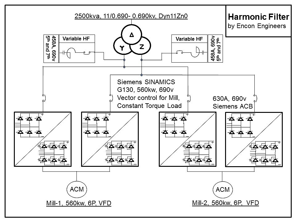
During the Yr.2013, 2sets each of 723A, 415v, tuned harmonic filters were installed at the duel secondary of the power plant's auxiliary VFD transformer of 2500kva, 11kv/415v- 415v. Dyn11Zn0 as show in Fig.5.
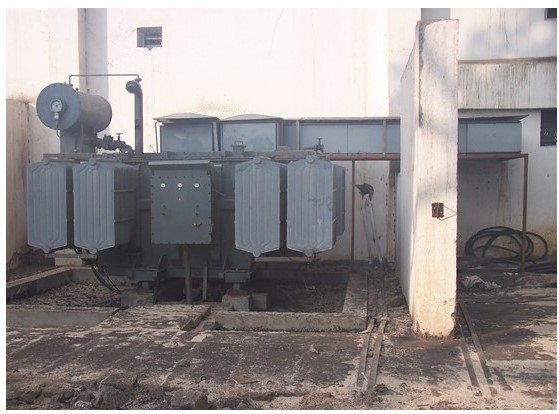
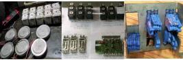
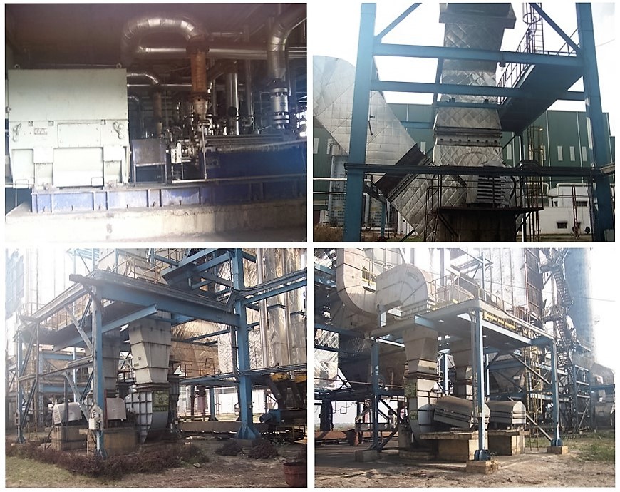
This VFD transformer supplies to all VFD drives which comprise of all nonlinear loads for this 25mw power plant's auxiliary supply. All VFD drives are of ABB ACS 800 make. Its single line diagram with the installed harmonic filters and VFD drive ratings are shown in Fig.6 (Top caption photo). The boiler's major VFD drives are namely boiler feed water pump (BFP), induced draft fan (IDF), forced draft fan (FDF) and supply air fan (SAF) are shown in Fig.4.
In-addition 1set 2400A, 415v tuned harmonic filter was installed at the secondary side of the 3150kva, 11/415v transformer which supplies to the sugar plant's process manufacturing section.
A detailed Power Quality harmonic measurement was carried out during Jan.2013 using a high quality 3phase power quality harmonic analyzer of type PowerPro. The instrument measures at a sampling rate of 256 samples/ cycle and calculates RMS value of all measured parameters at every cycle basis. It measures all steady state power parameters and power quality that including individual phase and neutral harmonics up to 64th, Total current harmonic distortion (THDi), Total voltage harmonic distortion (THDv), switching Inrush current, waveforms, voltage and current spikes, sags, swells and voltage fluctuations with 65uS precision recording. Further details of the instrument can be obtained at www.candura.com.
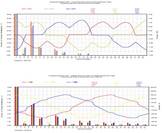
The current and voltage harmonic distortions and its waveforms at the 415v VFD transformer secondary PCC which supplies power to all ABB ACS800 VFD drives for the power plant auxiliary loads are as shown in Fig.7, before installation of the 2sets Tuned Harmonic Filters at the 2500kva two secondary three winding transformer. Because of major nonlinear loads in the form of VFDs, the harmonic distortions were very high. The total current harmonic distortion (THDi) was at 36% with I5, I7, and I11 as major current harmonics. The total voltage harmonic distortion (THDv) was at 6% with I5, I11, and I7 as major voltage harmonics.
The current and voltage harmonic distortions and its waveforms at the 415v VFD transformer secondary PCC which supplies power to all ABB ACS800 VFD drives for the power plant auxiliary loads are as shown in Fig.8, after installation of the 2sets Tuned Harmonic Filters at the 2500kva two secondary three winding transformer. Post harmonic filter scenario the harmonic distortions of both current and voltage harmonics were fully mitigated. The total current harmonic distortion (THDi) was at 8% with I5, I7, and I11 as major current harmonics. The total voltage harmonic distortion (THDv) was at 1% with I5, I11, and I7 as major voltage harmonics.
Simultaneously, a similar harmonic distortion mitigation results for both current and voltage harmonics were also achieved after the installation of the 2400A tuned harmonic filter at the 3150kva, 11kv/ 415v, Dyn11 transformer for the sugar plant's process manufacturing loads. Because of these power quality harmonic mitigations, the factory's major problem of repetitive electrical blasts got eliminated and did not repeat thereafter. In-addition it also solved the tripping problem with the power plant and with other process loads that used to happen whenever there used to be some grid voltage fluctuations and voltage sags.
Considering the enormous and frightening issue of electrical blasts that happened repeatedly before the installation of harmonic filters across the power plant and sugar plant process loads, post solutions, the factory's electrical power system was thoroughly analyzed for any possible indication that might still need to be tackled. Apart from power quality harmonic measurements, we also tracked other physical evidences, if any, and such details are usually best known to the plant operators.
And we have received one such important feedback on physical verification. During the days of electrical blasts, there used to be occasional incidents of power frequency oscillations. These oscillations were more pronounced, and was clearly visible, in the analogue frequency meters. Post commissioning of the harmonic filters, there was no such frequency oscillation observed. Another physical verification was with the seemingly funny incident of stagnant water boiling at the neutral earth pit of the 2500kva, 11kv/415v -415v, Dyn11Zn0, VFD transformer which was observed by chance with the blessings of the rain god showering at the same time of the incident. This phenomenon did not repeat after the implementation of the harmonic solutions.
Physical verification is an essential process for an effective troubleshooting engineer. These feedbacks are the difference between a "job well done" and a "job is in process".
Furthermore, during the Yr.2014, and fresh from the effective troubleshooting experience with its VFD card failures for the ABB ACS 800 VFD drives in the power plant auxiliaries and elimination of Electrical blasts, the factory installed yet another 4sets of tuned 458A, 690V harmonic filters across each of 560kw, 690v VFD drives for Mill-1, 2, 3 and 4.
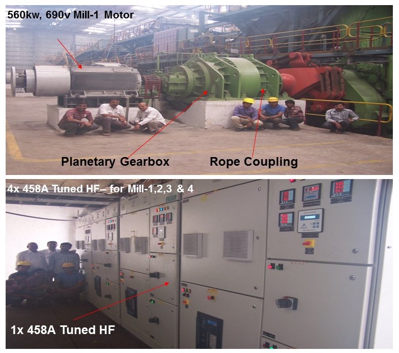
The four mill motors are fed from 2nos three winding transformers of capacity 2500kva, 11kv/690v-690v, Dyn11Zn0 which is similar as the rating of the power plant VFD transformer except for the secondary voltage. Mitigating and cleaning up VFD harmonics right from its point of generation at 690v which is also the VFD's input power terminal, increases its milling capacity by a ballpark figure of 30%. In the past, and since few decades, we have installed over several dozens of harmonic filters across such 12pulse drives at various medium voltage ratings most of which were 690v.
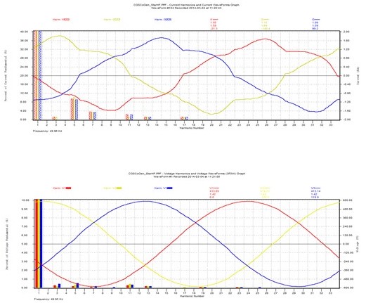
The current harmonic distortions and its waveforms at the 690v Mill VFD transformer secondary PCC which supplies power to Siemens Sinamics VFD drives for each of the mill drives is as shown in Fig.11, before and after the installation of Tuned Harmonic Filter for Mill-1. The first mill, the mill-1 and the last mill, the mill-4 are always loaded 20-40% higher than that of other mills in the middle. The total current harmonic distortion (THDi) was at 76% with I5, I7, and I11 as major current harmonics before the installation of harmonic filter, and after its installation the total current harmonic distortion reduced at 27% with I5, I7, and I11 as major current harmonics.
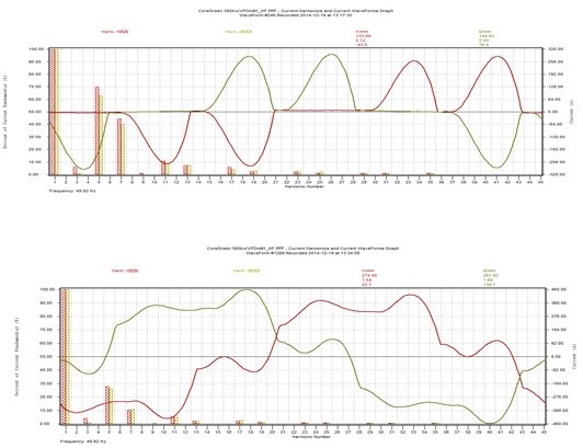
An important point to note here is, the harmonic numbers with 12pulse VFD drive. Theoretically it should have 11th and 13th as major harmonics but what we measured here are 5th and 7th as major harmonics and 11th and 13th as minor harmonics which are even negligible. Why this happens? The reason is quite simple. When we say 12pulse VFD drive, we get a 12pulse effect only at the Mill VFD transformer's primary side. Which is here 11kv PCC. But at the load point at VFD motor terminals, at the double secondary side (here 690v) of the three-winding transformer, and at the VFD drive itself, the harmonic number remains of 6-pulse type and thus we have correctly measured it as 5th and 7th as major harmonics. The VFD drive itself is a 6pulse drive. It is the double secondary of the three-winding transformer, and not the VFD drive, that generates the 12pulse effect at high voltage primary side.
Post harmonic solutions, as sheen in Fig.11, the harmonics at the 690v motor terminal reduced substantially from 76% to 27% with an overall improvement in motor terminal power quality, which reconstructed the heavily distorted waveform back into near a sinusoidal waveform.
The next step, besides power quality harmonic measurement of a well done harmonic distortion correction project is physical verification. We have observed noise, vibration, and running temperature of the 560kw, 690v VFD mill motor closely before and after commissioning of the 458A, 690v harmonic filter across it. By listening to vibrations using simple screwdriver method, and sensing with bare hands and ears, the reduction in motor's vibration, noise and temperature was distinctly verifiable and found quiet substantial.
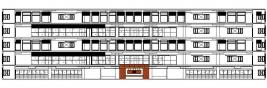
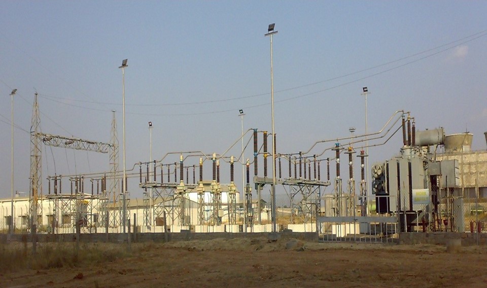
But after the new installation unexpectedly a new problem surfaced which was increasingly becoming difficult to diagnose. However, it was restricted only to Mill-1&2 section VFD Drives and did not occur with the other section of Mil-3&4 VFD drives. While commissioning the 690v harmonic filters, months ago, we observed Mill-1&2 VFD drives tripped couple of times on earth fault. On detailed check the plant personnel does not get any clue of it, and restarted the drive, and this process continues. It was thus considered merely a localized issue, and not with the plant's entire electrical power system. It's main incoming substation is as shown in Fig.12.
The Mill-1 VFD drive has 2sets of 630A, 690v, incoming ACB, as shown in Fig.9, and either one of them was tripping randomly on earth fault. It in turn was tripping the Mill's two parallel VFD drives, one at the Star side and another at the Zig-Zag side of its 3-winding Mill VFD transformer.
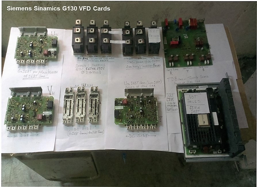
After usual maintenance check and since no earth fault could be found the VFD drives were reset and restarted at every such instance. It continued until at one such restart the entire two parallel VFD drive cards blasted heavily. Almost all converter thyristors and inverter IGBTs blasted off, as shown in Fig.13. The short circuit inside the VFD panel was so heavy that its upstream ACB's arc chute got blackened from interrupting a huge short circuit current.
The damage was so heavy and complete that the OEM took several days in organizing spares and reassembling the blasted VFD in its working condition. After carrying out mandated checks the OEM engineer switched ON the drive but within 30 minutes it tripped again, on the same old earth fault, which is annunciated through a low DC voltage fault in the VFD panel.
After working so hard around the clock for several days no one expected to come back to square one. It was evident that the same old root cause persisted. It would not be wise to restart the drive without a satisfactory diagnosis. The OEM once again performed all its recommended tests, checked megger values for Motor, Cable, Bus Bar and still there was no trace of the elusive earth fault, and everyone was at it wit's end.
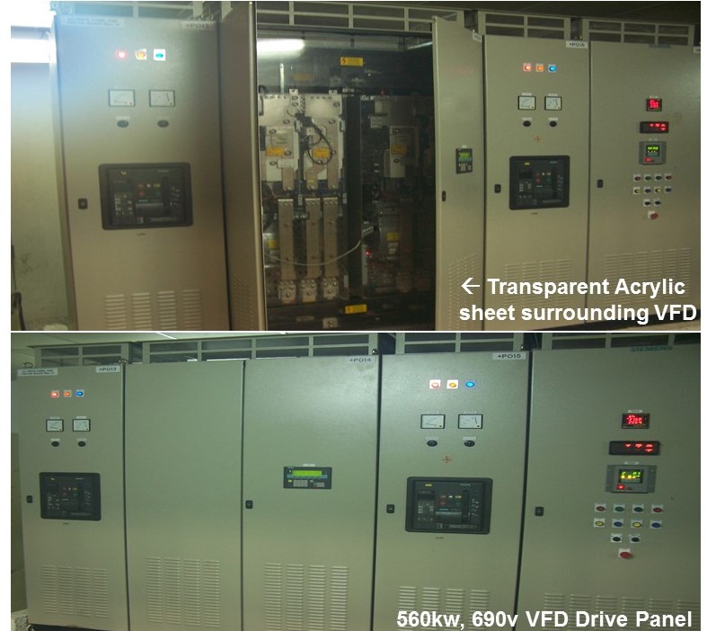
Finally, the root cause emerged. Our engineering design practice extensively use transparent Acrylic sheet and Hylam insulation sheet in panels for touch voltage protections, and further complicating the practice, there are several national and international standards that give us little choice but to use those for human safety against accidental touch voltage.
The problem with these sheets, that we had faced in the past, is that a thin layer of electrically conductive air is formed all along inside the Acrylic and Hylam Sheets which remains in near contact status with bare electrical bus bars and other live components of the VFD drive. This phenomenon happens due to a combination of factors. Those include trapped air in the surrounding, loose contacts in the VFD panel's power circuit, and those in conjunction with dust and a prolonged exposure in harmonic rich environment. We observed pitting at the terminal end of the bus bar and heavy arc flash mark at the inside surface of the Acrylic sheet that was closer to the live bus bar.
Further complicating the problem, the OEM has much reduced the dielectric insulation clearance from the required distance of IEC 61439 standard, ostensibly to reduce equipment footprint. In view of these finding our engineering practices concerning with touch voltage protections and dielectric insulation clearances are bound to take a material shift.
Eventually with the root cause identified and associated precautions taken to the extent feasible given the stated facts, it brought instant relief and joy to the project team that comprised of engineers from several companies across India. It instilled the much-needed courage and the confidence in restarting the Mill-1 VFD drive once again. And the plant management happy with the outcome arranged for a Krishan River Fish curry dinner party, a local delicacy for the project team.
IV. CONCLUSION
The enumerated case study and its yearlong performance verification report clearly establish all round improvement of major power system parameters for the plant's total power management, safely and without electrical blast.
Going by the saying what goes around comes around, it reconfirms the fact that doing power quality engineering at the downstream, at the point of harmonic generation of VFD drives either collectively or individually (which is 415v and 690v in this case study) mirrors optimum power system stability both within the plant and within its connected grid supply zone.
Such an engineering effort prevents electrical harmonic pollutions from entering the electrical power system of the grid supply zone which could then percolate into another plant's electrical power system. Which could create a similar problem of electrical blast or tripping or equipment failure.
In-addition, it reduces carbon emission by enhancing productivity, removing barriers to energy efficiency, and promoting efficient use of energy all along. That starts from downstream plant to neighboring users, and up to the upstream power plant, the IPP power supplier and the grid company.
The cost saving when looked narrowly in comparison with the electricity bill alone might seem moderate, but when compared holistically with substantially reduced investment cost, lower carbon footprint, uninterrupted production, MTBF, inventory cost of components and workforce motivation coupled with the ever rising cost of energy, the economic benefits far outweigh the cost of the solution.
 V. BIOGRAPHIES
Kanai Banerjee graduated in Electrical Engineering from Indian Institute of Engineering Science and Technology, Shibpur, India in the year 1983. Worked at Bharat Heavy Electricals Limited from 1983 to 1995 and thereafter until date, as a promoter at Encon Engineers (www.enconengineers.in/) at Bangalore.
His special fields of interest include power quality engineering, harmonic solutions and manufacturing passive tuned harmonic filter and triplen harmonic filter of all size LV and HV, troubleshooting failures, energy conservation, electrical consultancy and HVAC engineering for setting up truly green building and retrofitting large centralized HVAC projects.
He has been instrumental in building up the company's impressive growth and reputation as a knowledge-based technology solution provider on power quality, energy efficiency, process optimization and in Total Power Management fields
An energy auditor certified by the bureau of energy efficiency under the ministry of power government of India, a member and chartered professional engineer with the institute of engineers, India, a member at the Indian society of heating, refrigerating and air-conditioning engineers, ISHRAE and a member at the Canadian and American EMTP-ATP user group.
Place: Bangalore
Date: 30 December 2014